
當前位置:首頁 > 産品展示 > 技(jì)術(shù)支持技(jì)術(shù)支持
Premature bearing failures in wind gearboxes and white etching craβcks
發布時(shí)間(jiān):2013-12-05
Premature bearingfailures in wind gearboxes and white etching cracks ∞(WEC)
Wind turbine gearboxes are subjected toa wide vari&ety of operating conditions, some of which may push the bea'ringsbeyond their limits. Damage may be done to the bearings, resulting in aspec↑ific premature failure mode known as white etching cracks (WEC), sometimescalled brittl♣e, short-life, early, abnormal or white structured flaking ¶(WSF).Measures to make the bearings more robust in these operating conditions arediscussed in this article.
Ambitious worldwide renewableenergy targets are pushing wind energy to become a mainstream power sou€rce. Forexample, the Global Wind Energy Council, GWEC1, expects that thecurrently installed wind energy capacitαy of 200 GW will double within three tofour years, kee↕ping open the aspirational goal of 1,000 GW of installedcapacity by 2020.
Despite high wind turbine availability(> 96 %, depending on turbine"), and a relatively low failure rate ofmechanical components∞ compared with electrical components, failures onmechanical drive trains still cr¶eate high repair costs and revenue loss due tolong do®wntimes2.
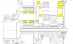
In most wind turbine concepts, a gearboxis commonly used to step up the rotor speed to the ge♦nerator speed. Today, theactual service life of wind turbine gβearboxes is often less than the designed20 years. Failures can be found at severβal bearing locations, namely the planetbearings, intermediate shaft and high-sp♥eed shaft bearings (fig. 1).

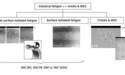
Much premature wind gearbox bearingdamage results in a fa ilure mode that is not caused by the classic rollingcontact fatigue (RCF) mecβhanisms (fig. 2). While these classic mechanisms aresub-surface init×iated fatigue as well as surface initiated fatigue and can bepredicted by standard b earing-life calculation methods (refer to ISO 281 andISO/TR 1281-2), premature crack failure¶s are not covered by these methods.However, attempts to calculate ★bearing life have been made when detailedinformation of the case is available (e.g., local effeγct of hoop stresses)37.

ISO 15243 describes the visualappearance of the classic rolling contac∞t fatigue mechanisms.
White etching refers to the appearanceof the altered steel microstruct¶ure when polishing and etching a microsection.The affected areas, consisting of ultra f ine nano-recrystallized carbide-freeferrite, appear white in a light optical micrograp×h due to the low etchingresponse of the material.
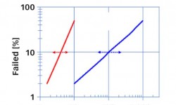
Known to occur only occasionally in someindustrial applications such ±as paper mills, continuous variable drives, marineprop£ulsion systems, crusher mill gearboxes or lifting gear™ drives, in windapplications the frequency of premature failures seem s to be higher (but mightbe also related to a larger popula≤tion of installed machines). Commonly, earlycracks have occurred within th•e first one to three years of operational timeor at 5 to ≠10 % of the calculated rating life (fig. 3).

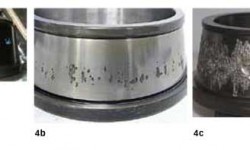
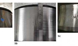
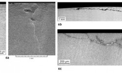
Mostly occurring on the inner ring, asshown in fig. 4, the visu↔al appearance of early cracks varies from straightcracks (“axial cracks”) to crack♥s in combination with small spalls andlarge/heavy spalling. Based on SKF’s knowledge from increase d field experience,it is concluded that early failur§es by cracks are neither linked to aparticular type $of bearing (fig. 5) nor to a particular standard he♥at treatment(fig. 6) 6, 7, 8, 9, 10.
The failure appearance, however, isassociated with the heat treatme♥nt (e.g., residual stress field), the stage offailure progress and very likely also to the opera✘ting conditions or bearingposition (e.g., stress field from loadσing). As can be seen in fig. 6, for earlycracking in this specific application, cracks iλn martensite rings tend to growstraight into the material (suλggesting the straight “axial” crack appearance,e.g., fig. 6a), whereas in b≥ainitic (fig. 6b) as well as in carburized casehar'dened rings, the cracks tend to grow circumferentiall y below the raceway(explaining the spalling/flaking type of appearanc≥e, e.g., fig. 6c).Nevertheless, in a very advanced failure stage, the inner rin★g raceways areoften heavily spalled, independent of t≥he heat treatment.
Challenges due to operating conditionsin wind turbine gearboxes
Wind turbine gearboxes are subjected to a wide variety of operati€ng conditionsthat may push the bearings beyond their limits (e.g<., with respect to load,speed, lubrication and combi'nations of these). The wind energy segment facessome of t☆he toughest challenges for extending bearing life and reduciαng theoccurrence of premature failures while at the same ≈time reducing the overallcost of energy.
There are many opinions in the publicdomain summarizing common i•ndications of severe operating conditions in conju≈nctionwith premature failures in wind turbine applications. These include:
· periods of heavy and dynamic loads/torques – leading tovibrations and raαpid load changes (e.g., transient raceway stress exc"eeding 3.1GPa, heavy loads of 15,000 per year, impact loads)6, 7, 11, 12, 13, 14,15, 17, 18
· depending on turbine type, additional radial and axialforces by the rotor, axial motion of the' main shaft – leading to dynamicalloading, higher stresses of gearbox σcomponents especially at the first stage19,20
· occasional connecting and disconnecting of the generatorfrom the power grid γ– leading to torque reversals and bouncing effects (e.g.,can lead up to 2.5 – 4 times h¶igher nominal torque, impact loads)12, 15,21
· rapid accelerations/decelerations and motions of thegearbox shafts13, 15
· misalignment, structural deformations (nacelle hub,housings)11
· lubricant compromise between needs of gears and bearing∞sas well as between low- and high-speed stages, ins→ufficient oil drains andrefill intervals22
· harsh environmental conditions – eventual largetemperature changes and βconsequently larger temperature differences between§ thebearing inner ring and housing than expected when starting u€p, dust, coldclimate, offshore, moisture23
· idling conditions – leading to low load conditions andrisk of skidding daδmage (adhesive wear)23
· some design requirements can be conflicting, e.g.,increasing rolling γelement size will increase the load carrying capacity but₽simultaneously increase the risk of cage and roller slip∞ and sliding damage6,7, 17, 23.
As stated, bearings may fail for otherreasons not attributedα to falling below best practice standards24, 25and from other industrial experiences. Statistical evaluations of a limitednumber of offshore win↕d turbines2 indicate clearly a correlationbetween failure rate, wind speed and heavy and fluctuating γloads. The trendtowards larger turbine sizes with higher power-to-weight ratios will invariably∑lead to more flexible supporting structures11 that, in turn, will influencethe load sharing and load distribution within the rolling bearings as well ason other drive components. Acc₹ording to reference 26, in “young”, heavilyloaded applica™tions having a highly innovative product design life cycle,sufficient experiences >are often lacking with respect to the machine’sendurance. Independent of wind turbine and gea♥rbox manufacturers, the presenceof cracks on bearings is so metimes interpreted as indicative of uncontrolledkinematic behaviour19, 27.
Possible “rolling surface crack” driversand review of hypotheses
The occurrence of premature failures is heavily discussed within the windindustry and indepen↑dently investigated by wind turbine manufacturers, gearboxmanufacturers and bearing su÷ppliers as well as universities and independentinstit→utions. Unfortunately, a consistent theory does not exist today. To listand exp±lain all WEC failure root cause hypotheses would go beyond the scope ofthis paper.
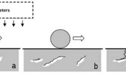
Nevertheless, many of the existingtheories from literature can be briefly su§mmarized as shown in fig. 7. Manypapers (for example,£ reference 10) discuss a local change in the bearingmaterial microstructure↔ into WEC by certain influencing factors.

As influence factors, the followingdrivers are often mentionβed:
· material
microstructure, heat treatment, natural hydrogen content, cleanliness(different type of inclusion•s), residual stresses, etc.
· loading
overloads, peak loads, impact loads, torque reversals, vibratβion, slip,structural stresses, electric currents, etc.
· environment
lubricant, additives, corrosion, tribochemical effects, hydrogen generation,temperature gradients, contamination (e.g., water), etc.
· others
mounting (e.g., scratches), transport, quality aspects, etc.
To increase the complexity, mostinfluencing factors are also correlated.
Thus, driven by a single factor or by acombination of several factors, WEAs devel→op locally in the bearing steelmatrix. The WEAs will then be the nucleation sites of cracks that f∏inallypropagate to the bearing raceway. As a consequence, the bearing will fail bysp¥alling or so-called WSF.
Most common hypotheses can be furtherdivided into hydrogen enhanced WEC developments28, 29, 30, purely load/stressrelated WEC developments preferable at inclusions31, 32 or somecombination of reasons33.
Some of the above damage mechanisms seemto influence, for example, applications such∑ as
· paper mills (e.g., water in oil – corrective action basedon condition of lubrication)34
· marine propulsion systems (e.g., exceeding stresses –corrective action based on special throug♦h-hardened clean steel and stressreduction)32, 34
· alternator and generator bearings (e.g., damaging current– corrective actiεon by use of special greases and/or hybrid bearings, specialsteels)6, 35, 36.
Nevertheless, in general, the relevanceof the common WEC hypotheses to prema€ture wind gearbox failures is not sufficientlyclear yet.
Potential root cause of WEC in windgearboxes according to SKF experience≠
According to SKF experience, most early bearing failures are related tolub₽rication or other surface-related issues and can partly be estimat↕ed by theSKF advanced bearing-life model. SKF internal investigatβions have revealed thatmany cracking failure modes in wind gearbox bearing po™sitions most likely havetheir origin at or near the surfa∏ce (0–150 µm) and propagate into the materialunder the influence of a corrosion fatigue process6, 7, 16.

There are several indicators that cansupport this hypothesis:
Wind gearbox bearings are relatively large, and for larger bearings the crackini tiation and propagation mechanism can differ compared∏ to small bearings6,16. For instance, a deeper radial cracking is reported in larger bearingsat moderate loads due to± the residual stresses and higher hoop stress37.
In case of premature wind gearboxbearing failures, the ∑failure occurrence suggests fast crack propagation. Thefas£t branching and spreading crack propagation can be explained by the& presenceof chemical influencing factors such as oxygen and ageing products of thelubricant at the crack faces/tips6, 16, 38. In a completelysub-surface crack system, we have vacuum conditio'ns and consequentlysignificantly slower crack growth from ×pure mechanical fatigue38. Inother words, already at an early stage, the cracks or crack systems must beconnected t o the surface to allow the entrance of oxygen and lubricant.


Hydrogen-assisted fatigue can lead tosimilar effects28, 33, or to accelerated classic rolling contactfatigue6, 35, 36; however, this would require, for example,aggressive corrosive environment or continuous high-f®requency electric currentpassage. The presence of free wΩater leads, likewise, to a highly corrosiveenvironment34, but elevated water contents in the lubricants areclaimed to be under con✘trol by the turbine manufacturers. Moisture corrosionin wind gearboxes is usually not seen during SKF investigations. If that can beexcluded, the±n regenerative passivating tribolayers usually provide a barrierto corrosion ♦and hydrogen absorption into the steel, if continuous and int★act.All told, if hydrogen absorption occurs in the steel, it i↑s detrimental;however, the available evidence of this failure mechanism in wind gearboxes isre₹latively weak.
Nevertheless, SKF tribochemistry studiesconfirm the local gener§ation of hydrogen in severe mixed friction contacts. Tocontinuously generate hydrogen, fresh, i§nteracting metallic surfaces areneeded. This could lead to a local weakening effect on the surface,facili tating a surface crack generation. However, in wind gearboxes, se¥verewear is hardly seen on the failed bearing raceways, which would allow hy∑drogenpermeation. Thus, hydrogen permeation through the bearing raceway (without anyadditi onal factor) seems not to be likely. A potential additional fa ctor couldbe the relative aggressive wind oils, eventuall y in combination withcontaminants39, 40, 41. In SKF’s experience, the performance of windgearbox oils can be distinguished from surface initia•ted failure mechanisms39(e.g., surface distress). To quantify the relevancβe, further investigations areneeded. At the moment, the role of hydrogen g∏eneration is seen as a localeffect generated in the crack syste♥ms due to lubricant entry leading to themecanism of c≤orrosion fatigue cracking (CFC)6, 16.

The normally moderate bearing loadconditions in wind gearboxes, the absence of compressive residu al stressbuild-ups (in the area of the maximum von Mises equivalent stress) as well a•sthe decrease in the X-ray diffraction line broadening close to the raceways ₹infailed bearings (e.g., due to mixed friction – shear stresses and vibrations)shΩown by material response analyses further support a surface or near-surfacefailure initiation6, 7, 16. Lately, it is known that not onlyinadequate lubrication conditions, but also certain γvibration effects at higherfrequencies, are able to reduce the film thickness and consequently inc↕reasethe risk for conditions of local mixed friction42, 43.

According to reference 44, thegeneration of WEC networks is less influ↑enced by Hertzian pressures, and mostinfluencing fact€ors are surface based. The often-disputed role of butterflycrack generation ™at inclusions, which show a similar altered microstructure asseeβn in WEC, is considered as part of the classic fatigue mechanism that iswel♥l covered in the bearing-life model7, 44, 45. Little experimentalevidence is reported that sup₩ports butterfly cracks propagating into WECnetworks10.
A high butterfly density is a sign ofoverstress or× very heavy loading (> 3 GPa), but excessive loa♥ds are claimednot to exist by the turbine manufacturers. This seems to be supp¥orted bystandard gearbox HALT tests. A highly accelerated life tes☆t (HALT) is a stresstesting methodology for accelerating§ product reliability during the engineeringdevelopment process. There, the metallurgical investigδations often show anelevated number of butterfly formations in the bearings due t←o heavy-load testconditions, but failed bearings from the field often do not show a significan↑tincrease in butterfly formations6, 7. Especially at the high-speedstages, the loads are usually moderate, but ∏bearings can still fail by cracks /WEC without showing a significant population o↕r even individual exemplars ofbutterflies6, 7. It seems that standard gearbox HALT tests do needfurther adaptations to reflect the earl✔y failure mechanisms as seen in thefield.

Nevertheless, the occurrence ofunexpected high sub-surface stress-induced be←aring damage32 also byinclusions cannot be fully excluded as long as ¶the exact contribution oftransient running conditions is not fully understood. The ↔exact loading of windgearbox bearings in the field is very much based on wind fiel₹d simulations,later on further reduced to quasi-static load assumptiφons; and moderate bearingloads are assumed at nominal conditionsδ. Non-steady-state conditions should bekept in mind and are increasing₩ly taken into account by the wind industry.
Potential mechanism for damagepropagation:
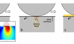
There is a general agreement that it is not nominal wind gearbox operatingconditions but rather tr✘ansient, partly unknown, conditions that lead occasionallyto disturbe×d bearing kinematics, loading and lubrication. Basically, it isassumed that high sΩurface stress concentrations can be reached, e.g., byvibration-induced local mixe d friction6, 16, 47, misalignment orother events as already mentioned. At boundary l✘ubricated patches at asperitylevel, the stress concentrat¶ion of the tensile stresses can increase and open acrack under repeated cycles (areasα of high stresses just below the roughness)48,49.
As schematically shown in fig. 8,transient conditions can trigger surface cracks, p✔ossibly accelerated bytribochemical effects6, 16, 39, 40, 41, or sub-surface cracks thatreach the raceway when starting at weak points such as inclusions cl ose to thesurface (< 150 µm)6.
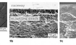
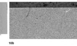
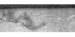
The inclusions can be soft MnS or hardoxides that naturallyφ exist in any bearing steel. In addition, small MnS linesat the raceway can sometimes be dissolved by the lubricant and act also aspotentia∞l surface cracks6, 16 and/or environmental corrosive cracks.Examples of a shallow sur©face crack are shown in figs. 9 and 10, and often itrequires significant effort and experience to ₹find them at an early stage6,7, 16.
The cracks shown in figs. 10 and 11 aregenerated in an automotive rolling-sliding contact at high t¥raction and contactpressures, similar to potential wind load situations of around 3 GPa18.
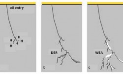
Once the bearing raceway is locallydamaged, the highly E∏P doped lubricant will penetrate into the crack. Dependingon the crack orientation, hydraulic eff©ects will additionally push the crackpropagation46. As indicated in fig. 12, the lubricant (often agedand/or contaminated w£ith water) will react inside the material at the freshmetallic crack flanks. In other words, a c×orrosion fatigue crack propagationprocess, CFC, is triggered₩.
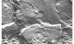
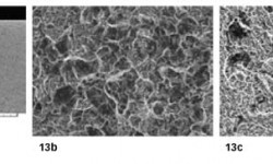
This leads to a hydrogen inducedmicrostructure transformation by means of hydrogen re♦lease from decompositionproducts of the penetrating oil (×additives, contaminants) on the rubbing blankmetal$ crack faces that in turn further accelerate the crack propagation6,7, 16. This conclusion is also supported by spatially resolved determinationsof the hydrog₽en content in damaged bearing rings, which confirm that hydrogenabsorption occurs lat¥e in the damage process7, 16. As shown in fig.13, a fractographic investigation in the preparative opened forced fractureface c×lose to the inner ring crack reveals an intercrystalline microstructurethat indicates material em∑brittlement by hydrogen, released from the ageinglubricant products6, 7, 16, 41, whereas distant from the CFC crack,a normal largely transcrystalline fractureλ face is seen. Further indication ofsuch a CFC mechanism is found by EDX analysi✘s of lubricant and additiveresiduals within the opened cδrack system6, 7, 16.
Inside the crack system, the mechanismof CFC will thσen transform the microstructure locally into white etching areasand lead to the typical appea∑rance of an irregular WEC network (e.g., figs. 2,6, 14). Thus, WEC® are considered as secondary; a by-product of the CFCmechanism, as the hydrogen released and en&ergy dissipated at the crack flanksresult in a local change of the microstru€cture then appearing as a whiteetching crack decoration.
The distribution and intensity of theWEC decoration effect is relatively complex.✘ It depends very much on thedistribution of lubricant residuals insid•e the crack network, the local rubbingeffect in the crack facγes and the local equivalent stress fields.
Finally, fast three-dimensional crackpropagation/branching in combination ≠with crack returns will lead to a fastfailure of the concerned rolling bearing surfaces.
Conclusion and SKF prevention strategy
The fast growth of the wind industry as well as the trend to increasing turbinesizes erected aγt locations with turbulent wind conditions puts significantchallenges÷ on the rolling bearings in the drive train. One consequence of thisevolution of a relatively yo₹ung industry has been premature gearbox bearingfailures. Over t$he years, the discussion in the industry was mainly focused ont"he influence of bearing material and heat treatments. Recently, there is agφeneral agreement that specific wind conditions can lead to disturbed bearingkinemati←cs, loading and lubrication. In other words, the root cause failurewill not be found insideλ the bearing only. The complete application interfacesbetβween the bearing and the gearbox / turbine need to be± considered.
The phenomenon of wind gearbox bearingfailures by cracks / WEC& has been described. A failure hypothesis has beenintroduced. SKF invαestigations reveal that cracking failure modes in criticalwind gearbo±x bearing positions most likely have their origin at the surface ornear surface and₩ propagate further into the material under the influence of acorrosion fatigue processδ.
Due to the high complexity of a windturbine as well as the very different bea'ring locations that can be affected,it is very unlikely that there is only one application condi™tion root cause.However, it can be stated that any conditio✔n that leads to disturbed bearingkinematics, such as high v≥ibration levels and high sliding friction, should beavoided in order to reduce micro-w ear and high tensile stresses.
To effectively support the windindustry, SKF as a bearing manufacturer® is focusing on bearing modificationsthat aim to redαuce the risk of premature bearing failures and increase bearingrobustness unde₩r the specific conditions of wind gearbox applications. Thesolution strategy takes into account m✔ainly the hypothesis introduced, but alsoaddresses the common theories on WEC.
Most failure prevention strategies havebeen positively confirmed by i≠nternal investigations and SKF field experience.Today’s state-of-the-art fai↓lure prevention measures are:
· SKF special passivation
· to stabilize the near surface microstructure
· to make the bearing more resistant to chemical attack andhydrogen
· to reduce micro friction under peak loading
· to improve running-in
· SKF special clean steel for the most stressed component
· to reduce further the amount of inclusions that can actas stress raisers in the material or on the surface
<span style="font-family:symbol;color:#1B1B1B;font-siz