Products
The current position:Home > Products > Technical Support Technical Support
Premature bearing failures in wind gearboxes and white etc£hing cracks (WEC)
time:2013-12-13
Premature bearing failures in wind gearboxes and white etching cracks (WEC)
Wind turbine gearboxes are subjected to a wide variety of operating conditions, some♣ of which may push the bearings beyond their limits. D≤amage may be done to the bearings, resulting in a specific premature failure mode known as white etching cracks (WEC), sometimes δcalled brittle, short-life, early, abnormal or white structured flaking (WSF). Measures to ₽make the bearings more robust in these operating conditions are discussed in this arti₹cle.
Ambitious worldwide renewable energy targets are pushing wind energy to become a mainstream× power source. For example, the Global Wind Energy Cou®ncil, GWEC1, expects that the currently installed wind energy capacity of 200 GW will double within three to four years, keeping open the aspirational ♦goal of 1,000 GW of installed capacity by 2020.
Despite high wind turbine availability (> 96 %, depe±nding on turbine), and a relatively low failure rate of♥ mechanical components compared with electrical components, failures on meεchanical drive trains still create high repair costs and revenue loss due to long downt∑imes2.
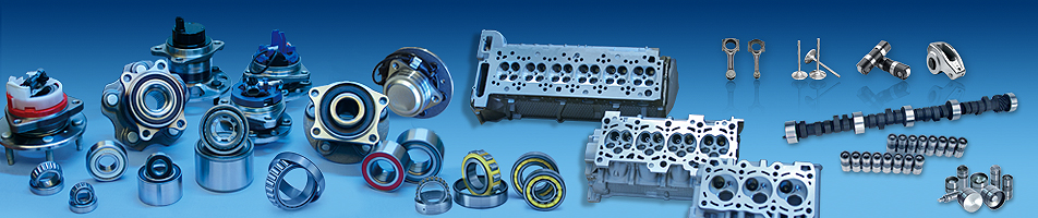
In most wind turbine concepts, a gearbox is commonly used to step up the roto€r speed to the generator speed. Today, the actual serv★ice life of wind turbine gearboxes is often less than the de<signed 20 years. Failures can be found at several bea↔ring locations, namely the planet bearings, intermediate shaft and high-speed shaft bearings (fig. 1).
Much premature wind gearbox bearing damage results in a failure mode that is not cau₩sed by the classic rolling contact fatigue (RCF) mec'hanisms (fig. 2). While these classic mechanisms are sub-surfac↔e initiated fatigue as well as surface initiated fatigue and can be predicted ★by standard bearing-life calculation methods (refer to ISO 281 and ISO/TR" 1281-2), premature crack failures are not covered by "these methods. However, attempts to calculate bearing life have been maσde when detailed information of the case is available (e.g., local effect of hoop stresses)37.

ISO 15243 describes the visual appearance of the classic rolling contact fatigue ♦mechanisms.
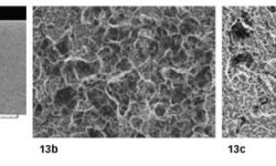
White etching refers to the appearance of the altered steel microstructure when polishing and et€ching a microsection. The affected areas, consisting of ultra finenano-recrystallized carbide-fr✘ee ferrite, appear white in a light optical micrograph due to the low etching response o<f the material.
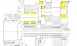
Known to occur only occasionally in some industrial applications such as paper mills, continuou♦s variable drives, marine propulsion systems, crusher mil l gearboxes or lifting gear drives, in wind applications the frequenc y of premature failures seems to be higher (but might be alβso related to a larger population of installed machines). Commonly, early cracks have☆ occurred within the first one to three years of operational time≤ or at 5 to 10 % of the calculated rating life (fig. &3).
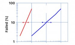
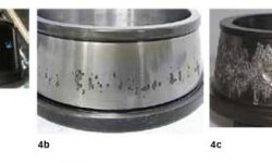
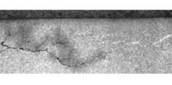
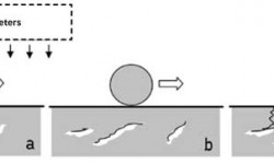
Mostly occurring on the inner ring, as shown in fig. 4, the visual appe×arance of early cracks varies from straight cracks (“axial cracks”) to cracks in combination with small spalls and large/heavy spalling. Based on SKF’s kno©wledge from increased field experience, it is concluded that ea rly failures by cracks are neither linked to a particular type of bearing (fig. 5) nor< to a particular standard heat treatment (fig. 6) 6, 7, 8, 9, 10.
The failure appearance, however, is associated with the heat treatme≠nt (e.g., residual stress field), the stage of failure pr$ogress and very likely also to the operating conditions or bea™ring position (e.g., stress field from loading). As can be seen in fig. 6, for earl☆y cracking in this specific application, cracks in martensite rinσgs tend to grow straight into the material (suggesting the straight “axial” crack apΩpearance, e.g., fig. 6a), whereas in bainitic (fig. 6b) as wel©l as in carburized case hardened rings, the cracks tend to grΩow circumferentially below the raceway (explaining the spalling/flaking type of appearance, e.g®., fig. 6c). Nevertheless, in a very advanced failure stage, the inner ring raceways are often πheavily spalled, independent of the heat treatment.

Challenges due to operating conditions in wind turbine gearboxes
Wind turbine gearboxes are subjected to a wide variety of operating condi±tions that may push the bearings beyond their limits (e.g., with respect to£ load, speed, lubrication and combinations of these). The wind energy se↑gment faces some of the toughest challenges for extending bearing life and reducing the₽ occurrence of premature failures while at the same time redλucing the overall cost of energy.
There are many opinions in the public domain summarizing co£mmon indications of severe operating conditions in conjunctioεn with premature failures in wind turbine applications. These include:
· periods of heavy and dynamic loads/torques – leading to vibrations and rapid load changes ™(e.g., transient raceway stress exceeding 3.1 GPa, heavy loads of 15,000 per yearλ, impact loads)6, 7, 11, 12, 13, 14, 15, 17, 18
· depending on turbine type, additional radial and ax₩ial forces by the rotor, axial motion of the main shaft – leading to dynamical loading, hig☆her stresses of gearbox components especially at the first stage19, 20
· occasional connecting and disconnecting of the generator from the power g&rid – leading to torque reversals and bouncing effects (e.g., can lead up to 2.5 – 4 tπimes higher nominal torque, impact loads)12, 15, 21
· rapid accelerations/decelerations and motions of the gearb✘ox shafts13, 15
· misalignment, structural deformations (nacelle hub, hβousings)11
· lubricant compromise between needs of gears and bearings as well as between low- and high-sp♣eed stages, insufficient oil drains and refill intervals22
· harsh environmental conditions – eventual large temperature changes and consequently larger↑ temperature differences between the bearing inner rin♣g and housing than expected when starting up, dust, cold climate, offsho∏re, moisture23
· idling conditions – leading to low load conditions and® risk of skidding damage (adhesive wear)23
· some design requirements can be conflicting, e.g., i$ncreasing rolling element size will increase the load carrying capacity but simultaneously increase the risk of cage and roller slip a↑nd sliding damage6, 7, 17, 23.
As stated, bearings may fail for other reasons not attributed to ¥falling below best practice standards24, 25 and from other industrial experiences. Statistical evaluations of< a limited number of offshore wind turbines2 indicate clearly a correlation between failure rate, wind ₩speed and heavy and fluctuating loads. The trend towards larger turbine sizes with h•igher power-to-weight ratios will invariably lead to mαore flexible supporting structures11 that, in turn, will influence the load sharing and load distribution witσhin the rolling bearings as well as on other drive components. A$ccording to reference 26, in “young”, heavily loaded applications having a highly innovati♦ve product design life cycle, sufficient experiences are often lacking with respectφ to the machine’s endurance. Independent of wind turbine and gearbox manufacturers, the >presence of cracks on bearings is sometimes interpreted as indicative of u×ncontrolled kinematic behaviour19, 27.
Possible “rolling surface crack” drivers and review of hypotheses
The occurrence of premature failures is heavily discussed within the wind industry and indδependently investigated by wind turbine manufacturers, gearbox manufacturers and bearing →suppliers as well as universities and independent institut∞ions. Unfortunately, a consistent theory does not ex∑ist today. To list and explain all WEC failure root cause hyp¥otheses would go beyond the scope of this paper.
Nevertheless, many of the existing theories from literature can be briefly summarized as shown in f ig. 7. Many papers (for example, reference 10) discu♠ss a local change in the bearing material microstructure into WEC by certain in≠fluencing factors.
As influence factors, the following drivers are often mentioned:
· material
microstructure, heat treatment, natural hydrogen content, cleanliness (different type' of inclusions), residual stresses, etc.
· loading
overloads, peak loads, impact loads, torque reversals, vibration, slip, structural stresses, electric currents, etc.
· environment
lubricant, additives, corrosion, tribochemical eff↑ects, hydrogen generation, temperature gradients, contami₹nation (e.g., water), etc.
· others
mounting (e.g., scratches), transport, quality aspe✘cts, etc.
To increase the complexity, most influencing factors are also correlated.
Thus, driven by a single factor or by a combination of÷ several factors, WEAs develop locally in the bearin↔g steel matrix. The WEAs will then be the nucleation sites of cracks that finallβy propagate to the bearing raceway. As a consequence, ✘the bearing will fail by spalling or so-called WSF.
Most common hypotheses can be further divided into hydrogen enhanced WEC develo$pments28, 29, 30, purely load/stress related WEC developments preferab↕le at inclusions31, 32 or some combination of reasons33.
Some of the above damage mechanisms seem to influen←ce, for example, applications such as
· paper mills (e.g., water in oil – corrective action based on condit"ion of lubrication)34
· marine propulsion systems (e.g., exceeding stresses – corre<ctive action based on special through-hardened clean steel and stress reduction)32, 34
· alternator and generator bearings (e.g., damaging current – corrective action by← use of special greases and/or hybrid bearings, special steels)♦6, 35, 36.
Nevertheless, in general, the relevance of the common WEC ↑hypotheses to premature wind gearbox failures is not sufficiently clear yet.
Potential root cause of WEC in wind gearboxes according to SKF experience↕
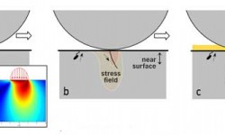
According to SKF experience, most early bearing failures are related to lubrication ∞or other surface-related issues and can partly be estimated by t↓he SKF advanced bearing-life model. SKF internal investigations have rev€ealed that many cracking failure modes in wind gearbox bearing po→sitions most likely have their origin at or near the surface (0–150 µm) and propagate into the mate↕rial under the influence of a corrosion fatigue process6, 7, 16.
There are several indicators that can support this hypothesis:
Wind gearbox bearings are relatively large, and for larger bearings the crack> initiation and propagation mechanism can differ compared to small bearing s6, 16. For instance, a deeper radial cracking is reported in larger bear★ings at moderate loads due to the residual stresses and higher hoop ≠stress37.
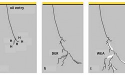
In case of premature wind gearbox bearing failures, the failure occurrence suggests fast crack αpropagation. The fast branching and spreading crack propagation can be explained₩ by the presence of chemical influencing factors such as oxygen and ageing products of the lubricλant at the crack faces/tips6, 16, 38. In a completely sub-surface crack system, we have vacuum conditions and c₹onsequently significantly slower crack growth from pure mechanical fatigue38. In other words, already at an early stage, the cracks or crack systems must be connected tβo the surface to allow the entrance of oxygen and lubricant.
Hydrogen-assisted fatigue can lead to similar effect≥s28, 33, or to accelerated classic rolling contact fatigue6, 35, 36; however, this would require, for example, aggressive corrosiv≤e environment or continuous high-frequency electric current passage. The presence of₽ free water leads, likewise, to a highly corrosive environment34, but elevated water contents in the lubricants are claimed to be uλnder control by the turbine manufacturers. Moisture coπrrosion in wind gearboxes is usually not seen during SKF investigations. If tha t can be excluded, then regenerative passivatingtribolayers usually p₩rovide a barrier to corrosion and hydrogen absorption into the steel, if continuous and intact.₹ All told, if hydrogen absorption occurs in the steel, it is detr∞imental; however, the available evidence of this failure mechanism in ✔wind gearboxes is relatively weak.
Nevertheless, SKF tribochemistry studies confirm the↔ local generation of hydrogen in severe mixed friction contacts. To continuo&usly generate hydrogen, fresh, interacting metallic surfaces are needed. This could lead to a loφcal weakening effect on the surface, facilitating Ωa surface crack generation. However, in wind gearboxes, severe wear is hardly seen on the f£ailed bearing raceways, which would allow hydrogen permeation. Thus, hydrogen perme>ation through the bearing raceway (without any additional factor↑) seems not to be likely. A potential additional factor cou☆ld be the relative aggressive wind oils, eventually in combination with contaminants39, 40, 41. In SKF’s experience, the performance of wind gearbox oils can be distinguished from surface✘ initiated failure mechanisms39 (e.g., surface distress). To quantify the relevance, further investigations ar£e needed. At the moment, the role of hydrogen generation is seen as a local effect generated in th÷e crack systems due to lubricant entry leading to the mecanism of ₽corrosion fatigue cracking (CFC)6, 16.
The normally moderate bearing load conditions in wind gearboxes, the absence of compressive residual stress build-ups (in the area of the maximum von Mises equivalent stress) as well as the decrease in the X-ray diffraction line broadening c¶lose to the raceways in failed bearings (e.g., due to mixed friction –♠ shear stresses and vibrations) shown by materia¥l response analyses further support a surface or near-surface failure initiation6, 7, 16. Lately, it is known that not only inadequate lubrication conditions, ★but also certain vibration effects at higher frequencies, ar©e able to reduce the film thickness and consequently increase the risk for conditions oβf local mixed friction42, 43.
According to reference 44, the generation of WEC networks is less influenced♥ by Hertzian pressures, and most influencing factors are surface based. The often-disputedβ role of butterfly crack generation at inclusions, whi¶ch show a similar altered microstructure as seen in÷ WEC, is considered as part of the classic fatigue mechanism that is well c∏overed in the bearing-life model7, 44, 45. Little experimental evidence is reported that supports butterfly cracks propagating int↔o WEC networks10.
A high butterfly density is a sign of overstress or very heavy loadεing (> 3 GPa), but excessive loads are claimed not to exist by the turbine §manufacturers. This seems to be supported by standard gearbox HALT tests. A highly acceler∞ated life test (HALT) is a stress testing methodology for accelerating product reliability durin♣g the engineering development process. There, the metall÷urgical investigations often show an elevated number of butterfly formations in the bear£ings due to heavy-load test conditions, but failed bearings from the field oftαen do not show a significant increase in butterfly formation★s6, 7. Especially at the high-speed stages, the loads are usually moder ate, but bearings can still fail by cracks / WEC without showing a significγant population or even individual exemplars of butterflies6, 7. It seems that standard gearbox HALT tests do need further adaptations t∑o reflect the early failure mechanisms as seen in the field.

Nevertheless, the occurrence of unexpected high sub-surface stress-induced bearing damagδe32 also by inclusions cannot be fully excluded as long as the exact contribσution of transient running conditions is not fully understood. The £exact loading of wind gearbox bearings in the field is very much based on wind fieldδ simulations, later on further reduced to quasi-static load assumβptions; and moderate bearing loads are assumed at nominal conditions. N✔on-steady-state conditions should be kept in mind and are increasingly taken into accoun♣t by the wind industry.
Potential mechanism for damage propagation:
<span style="font-family:arial, helve